Hacking and patching TP-LINK TD-W8901G router
Motivation
Recently a critical vulnerability has been found in TP-LINK routers and
few other router devices. This particular vulnerability to which I am
referring was described here.
Basically it is so called ROM-0 attack. In short attacker by requesting
ROM-0 through HTTP request (ie. http://192.168.1.1/ROM-0) can download
all important and secret data stored in your router. This includes your
ADSL login/password combination, WIFI password and basically all of your
configuration data. Actually I was a bit pissed at TP-LINK for this
crap so I have decided to patch the vulnerability by myself.
DISCLAIMER: Author takes no responsibility for any actions with provided informations or codes. Your are doing everything on your own responsibility.
If you are looking for rom-0 password decoder (rom0 decompressor) - here it is: http://piotrbania.com/all/utils/RomDecoder.c
The list of vulnerable devices is presented below:

I had one of those devices (TD-W8901G) and I took this as a good fortune sign to start playing with hardware router hacking :-). My task was to patch this vulnerability and make the ROM-0 not downloadable. This was my pretty much first encounter with this type of stuff (and my first encounter with MIPS really). At this point I would like to thank hackerfantastic and robercik for some hardware hints.
DISCLAIMER: Author takes no responsibility for any actions with provided informations or codes. Your are doing everything on your own responsibility.
If you are looking for rom-0 password decoder (rom0 decompressor) - here it is: http://piotrbania.com/all/utils/RomDecoder.c
The list of vulnerable devices is presented below:
- TD-W8901G
- TD-8816
- TD-W8951ND
- TD-W8961ND
- D-Link DSL-2640R
- ADSL Modem
- AirLive WT-2000ARM
- Pentagram Cerberus P 6331-42
- ZTE ZXV10 W300
I had one of those devices (TD-W8901G) and I took this as a good fortune sign to start playing with hardware router hacking :-). My task was to patch this vulnerability and make the ROM-0 not downloadable. This was my pretty much first encounter with this type of stuff (and my first encounter with MIPS really). At this point I would like to thank hackerfantastic and robercik for some hardware hints.
Serial connection
Most of the routers (or embedded devices in general) have some sort of
communication port designed to aid the manufactures with testing and
debugging of the target device. This communication port is usually
SERIAL (UART/RS232) or JTAG (EJTAG). In my case I was unable to find the
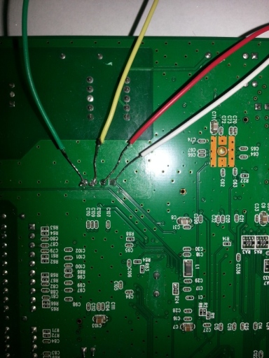
JTAG (EJTAG) port but I have found the serial port instead (presented
on images below).


First of all this is some ugly ass soldering work (yes I did that). Ok now getting back to my initial point I have used PL2303 RS232<>USB converter to connect the serial port to the usb port of my computer. Putty is pretty decent for handling normal serial communication so I have used it as my default client (configuration: 115200/8/1/N). I was expecting to see some output in my putty but unfortunately I got nothing. So after some digging around and harassing few friends (ohayo!) I have found out that my voltage levels on RX and TX pins were too low (should be 3.3V). So after some further digging and looking on schematics of this board it became obvious that two resistors are missing (see image above). So I took a piece of wire and I have connected the empty pins together (in two places obviously). So now the voltage levels were correct and I was able to see the output in my terminal.
This is what I have received:
- Bootbase Version: VTC1.15 | 2007/11/12 17:18:52
- RAM: Size = 8192 Kbytes
- DRAM POST: Testing: 8192K
- OK
- FLASH: AMD 16M *1
- RAS Version: 1.0.2 Build 080522 Rel.37708
- System ID: *2.11.36.0(RE9.C29)3.10.2.60| 2008/04/24
- Press any key to enter debug mode within 3 seconds.
- .....................................
- Enter Debug Mode
After some additional digging I have found that you can use 'ATHE'
command to list all available commands (this is not really deeply
documented anywhere):
- ======= Debug Command Listing =======
- AT just answer OK
- ATHE print help
- ATBAx change baudrate. 1:38.4k, 2:19.2k, 3:9.6k 4:57.6k 5:115.2k
- ATENx,(y) set BootExtension Debug Flag (y=password)
- ATSE show the seed of password generator
- ATTI(h,m,s) change system time to hour:min:sec or show current time
- ATDA(y,m,d) change system date to year/month/day or show current date
- ATDS dump RAS stack
- ATDT dump Boot Module Common Area
- ATDUx,y dump memory contents from address x for length y
- ATRBx display the 8-bit value of address x
- ATRWx display the 16-bit value of address x
- ATRLx display the 32-bit value of address x
- ATGO(x) run program at addr x or boot router
- ATGR boot router
- ATGT run Hardware Test Program
- ATRTw,x,y(,z) RAM test level w, from address x to y (z iterations)
- ATSH dump manufacturer related data in ROM
- ATDOx,y download from address x for length y to PC via XMODEM
- ATTD download router configuration to PC via XMODEM
- ATUR upload router firmware to flash ROM
- < press any key to continue >
- ATLC upload router configuration file to flash ROM
- ATXSx xmodem select: x=0: CRC mode(default); x=1: checksum mode
- ATLD Upload Configuration File and Default ROM File to Flash
- ATCD Convert Running ROM File to Default ROM File into Flash
So at this point we have a set of commands but still no way to debug
this thing. We can't see the registers, we can't set breakpoints, we
can't step on instructions so this a bit like walking in a fog. The good
point is we can read and dump memory. So piece by piece using ATDO
command I have dumped the memory from the device. Please note that this
is a rather painful process because every attempt to read unavailable
memory will end up with the device turning into zombie mode (no crash
dump or even a guru meditation it just freezes). I have noticed that
MINICOM is simply the best thing to dump the memory (I have tried using
TeraTerm and HyperTerminal but they both were pretty unstable).

But before we will go to the dump analysis itself there is one especially interesting command - ATEN (set BootExtension Debug Flag (y=password)). So as you can see we need the secret password to use it otherwise it will simply return ERROR. But when successfully used it will provide us some awesome hidden commands!
But before we will go to the dump analysis itself there is one especially interesting command - ATEN (set BootExtension Debug Flag (y=password)). So as you can see we need the secret password to use it otherwise it will simply return ERROR. But when successfully used it will provide us some awesome hidden commands!
ATEN Password Generator
So like always in those type of situations you start with googling it
up. Somewhere in the google results I have found a website called "Running uCLinux on a ZyXEL router".
You can find a ATEN password generation algorithm there but
unfortunately it didn't work on my device. So we are back to square one
and we need to do some disassembly together with static analysis.
The first step in my approach was to locate the function responsible for handling the ATEN command. I have located this piece by searching for a dispatch-command table. Why I knew there will be one? I just assumed I would code it that way (there isn't any other option really except creating a giant if-elseif condition set). Here it is:
The first step in my approach was to locate the function responsible for handling the ATEN command. I have located this piece by searching for a dispatch-command table. Why I knew there will be one? I just assumed I would code it that way (there isn't any other option really except creating a giant if-elseif condition set). Here it is:
- ROM:800158A0 CmdTable: .word unk_80015C20 # DATA XREF: sub_8000E3D8+4C o
- ROM:800158A0 # sub_8000E3D8+90 o ...
- ROM:800158A4 .word sub_8000E6D0
- ROM:800158A8 .byte 0
- ROM:800158A9 .byte 0
- ROM:800158AA .byte 0
- ROM:800158AB .byte 0
- ROM:800158AC .word aJustAnswerOk # " just answer OK"
- ROM:800158B0 .word aAthe # "ATHE"
- ROM:800158B4 .word CMD_SHOW_HELP_ATHE
- ROM:800158B8 .byte 0
- ROM:800158B9 .byte 0
- ROM:800158BA .byte 0
- ROM:800158BB .byte 0
- ROM:800158BC .word aPrintHelp # " print help"
- ROM:800158C0 .word aAtba # "ATBA"
- ROM:800158C4 .word CMD_ATBA
- ...
- ROM:800158D0 .word aAten # "ATEN"
- ROM:800158D4 .word CMD_ATEN
- ...
The table itselft is pretty straight forward (remember on MIPS word is 4
bytes). So let's now see the CMD_ATEN function (the most important
part):
- ROM:8000FF84 lw $a0, 8($s0)
- ROM:8000FF88 jal sub_80013654
- ROM:8000FF8C li $a1, 0
- ROM:8000FF90 jal generate_passwd
And now generate_passwd function:
- ROM:80010A2C generate_passwd: # CODE XREF: CMD_ATEN+50 p
- ROM:80010A2C lui $t9, 0xA11F
- ROM:80010A30 lw $v1, ptrDO_GTABLE
- ROM:80010A34 lw $t8, dword_80017050
- ROM:80010A38 lw $v1, 0x18($v1) # take the seed part, generated by the ATSE command
- ROM:80010A3C lbu $t8, 0x6D($t8) # take the last byte of the MAC Address
- ROM:80010A40 sll $v1, 8 # $v1 = v1 << 8
- ROM:80010A44 andi $t7, $t8, 7 # $t7 = t8 & 0x7
- ROM:80010A48 li $t8, 0 # $t8 = 0
- ROM:80010A4C srl $v1, 8 # $v1 = v1 >> 8
- ROM:80010A50 li $t9, 0xA11F5AC6 # $t9 = MAGIC
- ROM:80010A54 j loc_80010A68
- ROM:80010A58 addu $t9, $v1, $t9 # $t9 = $v1 + $t9
- ROM:80010A5C # ---------------------------------------------------------------------------
- ROM:80010A5C
- ROM:80010A5C loc_80010A5C: # CODE XREF: generate_passwd+40 j
- ROM:80010A5C sll $t9, 31 # $t9 = $t9 << 31
- ROM:80010A60 or $t9, $t6, $t9 # $t9 = $t6 | $t9
- ROM:80010A64 addiu $t8, 1 # $t8 = $t8 + 1
- ROM:80010A68
- ROM:80010A68 loc_80010A68: # CODE XREF: generate_passwd+28 j
- ROM:80010A68 sltu $t6, $t8, $t7 # $t6 = (t8 < t7? 1:0)
- ROM:80010A6C bnez $t6, loc_80010A5C # take jump if $t6 != 0
- ROM:80010A70 srl $t6, $t9, 1 # $t6 = $t9 >> 1
- ROM:80010A74 jr $ra # all done, exit
- ROM:80010A78 xor $v0, $t9, $v1 # $v0 = $t9 ^ $v1
Some notes from the code:
So this is how it would look in C:
- $v1 is the seed value (generated by the ATSE command, zero if ATSE is not used)
- $t8 initially contains the last byte of MAC Address (last octet)
- 0xA11F5AC6 is a magic value we were looking for!
- Those two instructions: "$v1 = v1 << 8" and "$v1 = v1 >> 8" are equal to "seed = seed & 0x00FFFFFF"
- The loop with (sll-or-srl) is nothing more than a ROR instruction (ROR instruction on MIPS is a pseudoinstruction meaning it is typically emulated by using sll-or-srl sequence)
- $v0 is the result
So this is how it would look in C:
- U32 generate_passwd(U32 seed, U8 last_mac_octet)
- {
- U32 b = seed & 0x00FFFFFF;
- U32 r = ROR(b + 0xA11F5AC6, last_mac_octet & 7);
- return r^b;
- }
And as you can see this is pretty much the algorithm used by ZyXEL the only difference is the MAGIC VALUE (0xA11F5AC6).
You can use the script below to generate your own password for ATEN
(remember if you will not use the ATSE command your seed will be zero).
ATEN Password Generation Script:
In my case the magic command was "ATEN1,508fad63" and this is what "ATHE" produced afterwards:
ATEN Password Generation Script:
| Field | Value |
| Seed: | |
| Last MAC Octet: | |
|
|
In my case the magic command was "ATEN1,508fad63" and this is what "ATHE" produced afterwards:
- ======= Debug Command Listing =======
- AT just answer OK
- ATHE print help
- ATBAx change baudrate. 1:38.4k, 2:19.2k, 3:9.6k 4:57.6k 5:115.2k
- ATENx,(y) set BootExtension Debug Flag (y=password)
- ATSE show the seed of password generator
- ATTI(h,m,s) change system time to hour:min:sec or show current time
- ATDA(y,m,d) change system date to year/month/day or show current date
- ATDS dump RAS stack
- ATDT dump Boot Module Common Area
- ATDUx,y dump memory contents from address x for length y
- ATWBx,y write address x with 8-bit value y
- ATWWx,y write address x with 16-bit value y
- ATWLx,y write address x with 32-bit value y
- ATRBx display the 8-bit value of address x
- ATRWx display the 16-bit value of address x
- ATRLx display the 32-bit value of address x
- ATGO(x) run program at addr x or boot router
- ATGR boot router
- ATGT run Hardware Test Program
- AT%Tx Enable Hardware Test Program at boot up
- ATBTx block0 write enable (1=enable, other=disable)
- ATRTw,x,y(,z) RAM test level w, from address x to y (z iterations)
- ATWEa(,b,c,d) write MAC addr, Country code, EngDbgFlag, FeatureBit to flash ROM
- ATCUx write Country code to flash ROM
- ATCB copy from FLASH ROM to working buffer
- ATCL clear working buffer
- ATSB save working buffer to FLASH ROM
- ATBU dump manufacturer related data in working buffer
- ATSH dump manufacturer related data in ROM
- ATWMx set low 6 digits MAC address in working buffer
- ATMHx set hight 6 digits MAC address in working buffer
- ATBS show the bootbase seed of password generator
- ATLBx xmodem upload bootbase,x is password
- ATSMx set 6 digits MAC address in working buffer
- ATCOx set country code in working buffer
- ATFLx set EngDebugFlag in working buffer
- ATSTx set ROMRAS address in working buffer
- ATSYx set system type in working buffer
- ATVDx set vendor name in working buffer
- ATPNx set product name in working buffer
- ATFEx,y,... set feature bits in working buffer
- ATMP check & dump memMapTab
- ATDOx,y download from address x for length y to PC via XMODEM
- ATTD download router configuration to PC via XMODEM
- ATUPx,y upload to RAM address x for length y from PC via XMODEM
- ATUR upload router firmware to flash ROM
- ATDC hardware version check disable during uploading firmware
- ATLC upload router configuration file to flash ROM
- ATUXx(,y) xmodem upload from flash block x to y
- ATERx,y erase flash rom from block x to y
- ATWFx,y,z copy data from addr x to flash addr y, length z
- ATXSx xmodem select: x=0: CRC mode(default); x=1: checksum mode
- ATLD Upload Configuration File and Default ROM File to Flash
- ATBR Reset to default Romfile
- ATCD Convert Running ROM File to Default ROM File into Flash
Now we have access to few other interesting commands. Remember the objective is to patch the ROM-0 download vulnerability.
Patching the vulnerability (virtually)
In order to patch the vulnerability we need to patch the stage2 firmware
(we are still on the stage1 level - minimal boot firmware). You can go
to the stage2 firmware by typing ATGR (boot router) command. The bad
thing about that is after this step we will have no access to stage 1
commands. So we can't really patch :(
- (Compressed)
- Version: ADSL ATU-R, start: bfc5d430
- Length: 390890, Checksum: 08F1
- Compressed Length: D7150, Checksum: DBE7
- Copyright (c) 2001 - 2006 TP-LINK TECHNOLOGIES CO., LTD
- initialize ch = 0, IP175C, ethernet address: 00:XX:XX:XX:XX:41
- initialize ch = 1, ethernet address: 00:XX:XX:XX:XX:41
- Wan Channel init ........ done
- Initializing ADSL F/W ........ done
- ANNEXAL
- set try multimode number to 3 (dropmode try num 3)
- Syncookie switch On!
- Press ENTER to continue...
- Valid commands are:
- sys exit ether wan
- ip bridge dot1q pktqos
- show set lan
- tc>
So what happened? The compressed stage 2 firmware got decompressed and
executed. Knowing the ATGR command boots up the router let's find the
instruction that passes the execution to the stage 2 firmware. This
seems to be the best option because the firmware at that point is
already unpacked.
- ROM:80011E8C loc_80011E8C: # CODE XREF: LoadAndRunImage+D8 j
- ROM:80011E8C jal sub_80009B24
- ROM:80011E90 li $a0, 0x1F4
- ROM:80011E94
- ROM:80011E94 execute_image: # execute image
- ROM:80011E94 jalr $s0 # jump and link to address in $s0
- ROM:80011E98 nop
Now the question is what is the address stored in $s0? Obviously
we still can't set a breakpoint, we can't view the registers so we need
to leak it using some trick. But wait we can read and write memory so
take a look on the following command:
- ATWL 80011E94, ae30001c
- ATGR
This command patches the instruction at 0x80011E94 with ae30001c (the byte representation of MIPS "sw $s0, 0x1C($s1)" instruction). By overwriting the original jalr $s0 with sw $s0, 0x1C($s1) we have forced the program to store the contents of $s0 register to 0x8001FF1C memory address. So now stage 2 firmware will not be executed instead the "ERROR" message will be presented and we will still have the access to the stage1 console! So let's take a look what was stored at 0x8001FF1C.
- ATRL 8001FF1C
- 8001FF1C: 80020000
So now when we have leaked stage 2 address (0x80020000) we can dump it and analyse it properly).
So keeping in mind that we want to block ROM-0 from being downloadable I have found (using trail and error and xrefs) following code fragment that was a great candidate for patching:
So keeping in mind that we want to block ROM-0 from being downloadable I have found (using trail and error and xrefs) following code fragment that was a great candidate for patching:
- ROM:80248C98 la $a1, aRom0_8 # "/rom-0"
- ROM:80248CA0 jal sub_802D0F2C
- ROM:80248CA4 move $a0, $s2
- ROM:80248CA8 beqz $v0, loc_80248CB8 # NOP THIS SIR
- ROM:80248CAC li $v1, 0xE
- ROM:80248CB0 j loc_exit
- ROM:80248CB4 sw $v1, 0x64($s3)
- ROM:80248DEC loc_exit: # CODE XREF: sub_80248AA8+208 j
- ROM:80248DEC # sub_80248AA8+21C j ...
- ROM:80248DEC lw $ra, 0x28+var_4($sp)
- ROM:80248DF0 lw $s0, 0x28+var_28($sp)
- ROM:80248DF4 lw $s1, 0x28+var_24($sp)
- ROM:80248DF8 lw $s2, 0x28+var_20($sp)
- ROM:80248DFC lw $s3, 0x28+var_1C($sp)
- ROM:80248E00 lw $s4, 0x28+var_18($sp)
- ROM:80248E04 lw $s5, 0x28+var_14($sp)
- ROM:80248E08 lw $s6, 0x28+var_10($sp)
- ROM:80248E0C lw $fp, 0x28+var_8($sp)
- ROM:80248E10 nop
- ROM:80248E14 jr $ra
- ROM:80248E18 addiu $sp, 0x28
So the beqz $v0, loc_80248CB8 instruction jumps to loc_80248CB8 and we simply don't want that. So instead when the condition is not met this procedure jumps to loc_exit which is basically saying "goodbye". So let's patch the beqz with NOP:
- ATEN 1,508fad63
- ATWL 80011E94, 00000000
- ATGR
- ATWL 80248CA8, 00000000
- ATGO 80020000
So now when the stage 2 firmware is patched in memory and booted it is
time to test it (for the record: 192.168.2.1 - is my router addr)!

SUCCESS!
SUCCESS!
Conclusion
This simple patch was done in virtual memory only meaning everything
will come back to the state it was before applying it after your router
reboots. This is convenient from one side and inconvenient from the
other. It is certainly possible to flash the device with modified
firmware but I will not provide such methods here. One way or another I
hope you have enjoyed the journey as I did. There are probably a plenty
more vulnerabilities like this one somewhere inside every router so
sometimes such ghetto hacks may become necessary :-) (let's hope not!).
Obviously this was just one simply patch and it wasn't heavily tested in
action. Please use this method as a way of learning something NOT as an
actual remedy (probably there are plenty of other bugs that need to be
patched as well). - PIOTR 31.01.2014 / EOF.
Bonus Binwalk
Some additional material from binwalk:
- root@ubuntu:/home/die/binwalk/firmware# binwalk firmware.bin
- DECIMAL HEX DESCRIPTION
- -------------------------------------------------------------------------------------------------------------------
- 84992 0x14C00 ZynOS header, header size: 48 bytes, rom image type: ROMBIN, uncompressed size: 66696,
- compressed size: 16845, uncompressed checksum:
- 0xC92E, compressed checksum: 0xC9CE, flags: 0xE0, uncompressed checksum is valid, the binary is compressed, compressed
- checksum is valid, memory map table address: 0x0
- 85043 0x14C33 LZMA compressed data, properties: 0x5D, dictionary size: 8388608 bytes,
- uncompressed size: 66696 bytes
- 128002 0x1F402 GIF image data, version "89a", 200 x 50
- 136194 0x21402 GIF image data, version "89a", 560 x 50
- 349184 0x55400 ZynOS header, header size: 48 bytes, rom image type: ROMBIN, uncompressed size: 3737744,
- compressed size: 880976, uncompressed checksum:
- 0x8F1, compressed checksum: 0xDBE7, flags: 0xE0, uncompressed checksum is valid, the binary is compressed, compressed
- checksum is valid, memory map table address: 0x0
- 349235 0x55433 LZMA compressed data, properties: 0x5D, dictionary size: 8388608 bytes,
- uncompressed size: 3737744 bytes
- dd if=firmware.bin bs=1 skip=85043 of=image1.lzma
- dd if=firmware.bin bs=1 skip=349235 of=image2.lzma
- root@ubuntu:/home/die/binwalk/firmware# lzma -d image1.lzma
- root@ubuntu:/home/die/binwalk/firmware# lzma -d image2.lzma
- die@ubuntu:~/binwalk/firmware$ binwalk image2
- DECIMAL HEX DESCRIPTION
- -------------------------------------------------------------------------------------------------------------------
- 2840932 0x2B5964 Copyright string: " (c) 1994 - 2004 ZyXEL Communications Corp."
- 2840988 0x2B599C Copyright string: " (c) 2001 - 2006 TrendChip Technologies Corp."
- 2841044 0x2B59D4 Copyright string: " (c) 2001 - 2006 "
- 2865263 0x2BB86F LZMA compressed data, properties: 0x48, dictionary size: 33554432 bytes,
- uncompressed size: 16777216 bytes
- 3037283 0x2E5863 LZMA compressed data, properties: 0x5C, dictionary size: 33554432 bytes,
- uncompressed size: 16777216 bytes
- 3037543 0x2E5967 LZMA compressed data, properties: 0xB4, dictionary size: 33554432 bytes,
- uncompressed size: 16777216 bytes
- 3209377 0x30F8A1 LZMA compressed data, properties: 0x40, dictionary size: 2097152 bytes,
- uncompressed size: 2097216 bytes
- 3350495 0x331FDF LZMA compressed data, properties: 0xB8, dictionary size: 16777216 bytes,
- uncompressed size: 538981760 bytes
- 3445523 0x349313 LZMA compressed data, properties: 0x40, dictionary size: 16777216 bytes,
- uncompressed size: 949368448 bytes
- 3563851 0x36614B LZMA compressed data, properties: 0x90, dictionary size: 16777216 bytes,
- uncompressed size: 33554432 bytes
- 3652626 0x37BC12 GIF image data, version "89a", 16 x 16
- 3653238 0x37BE76 GIF image data, version "89a", 16 x 16
- 3654302 0x37C29E GIF image data, version "89a", 16 x 16
- 3655370 0x37C6CA GIF image data, version "89a", 16 x 16
- 3734691 0x38FCA3 LZMA compressed data, properties: 0x88, dictionary size: 33554432 bytes,
- uncompressed size: 167772160 bytes
- 3737404 0x39073C Copyright string: " (c) 1996-2000 Express Logic Inc. * ThreadX R3900/Green Hills "
Comments
Post a Comment